Telephone: 408-839-5569
Email: (Click Here) Andrew@JaguarSpecialties.com
Last Update 7-2-24
|
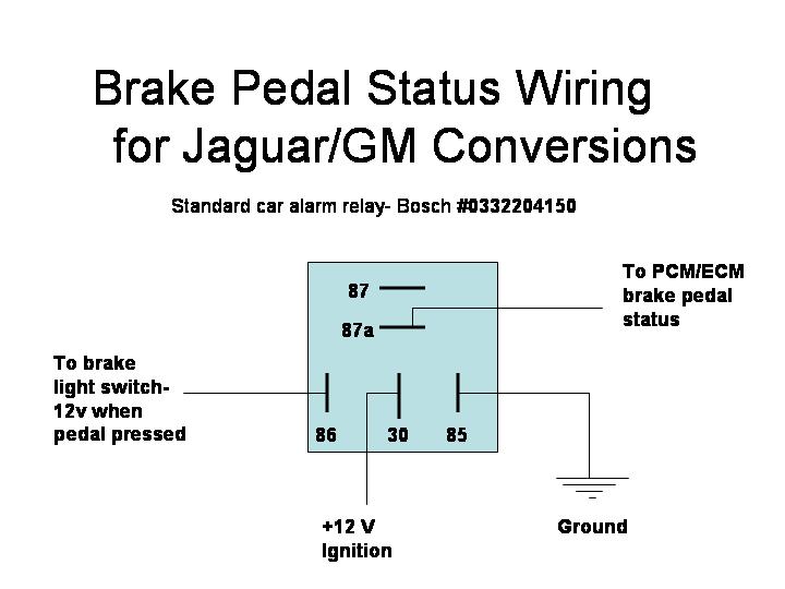
Tech Tip #5- Brake Pedal Status Wiring for Engine Conversions All late model GM transmissions (from 94 and up) use all electronic control for shift points, shift firmness, etc.,. This means that the engine computer (referred to as the PCM) completely controls the transmission as opposed to the mechanical governors and throttle valve cable used on earlier models. One of these computer controlled functions is the torque converter lockup feature, designed to lock the torque converter in steady state cruising modes, which greatly improves fuel economy. To do this properly, the PCM requires a number of inputs from the engine and vehicle, and one of them is the status of the brake pedal. Simply put, the PCM does not want the torque converter to be locked when driver presses the brake pedal. If for example in a panic stop the driver locked up the rear wheels, a converter that remained locked up could stall the engine, losing power steering and power brake control. So to avoid this potentially dangerous situation, the PCM takes a signal, typically through the brake light switch circuit, that tells it if the brake pedal has been pressed. This sounds simple enough, but the logic is reversed from what you’d expect. In normal driving (brake pedal at rest, or not pressed), the PCM expects to see a 12V signal on this line, and then see a 0V signal when the brake pedal is pressed. This is of course opposite of how brake lights are typically wired. To get around this, all that is required is a standard Bosch fog lamp or car alarm relay, part number 0332204150. This relay has both normally open and normally closed contacts, meaning it can take an external signal to make a connection, or break it. In this case, we want the to wire into the Jaguar brake light circuit, and use that signal to break the 12V brake pedal status signal when the brake pedal is pressed. Attached is a simple wiring schematic to provide this logic. One important point to make note of is that the power input to the relay (terminal 30) needs to be an ignition hot source, one that is only 12V when the key is in the run position. If this was a battery hot source (12V all the time) then the relay would be supplying 12V to the PCM at all times (even when the car was not running) which would eventually drain the battery. As you can see, the circuit is fairly simple and is a snap to set up. Once this circuit is in place, the PCM will see the correct brake pedal status signal logic (12V with brake pedal at rest, and 0V when the pedal is pressed). Before driving the car, verify that the logic is correct with a test light, and then you’re good to go. One final note: for conversions using the earlier T700R4 transmission (also with torque converter lockup), this wiring strategy can be used to power the torque converter clutch lockup. While no PCM (or ECM as earlier computers are know) is required for this earlier transmission’s operation, the torque converter clutch lockup feature does require a 12V ignition feed, and this circuit has the proper logic to work in that application. In these applications, terminal 87a would be connected directly to the torque converter lockup power input on the T700R4.
|